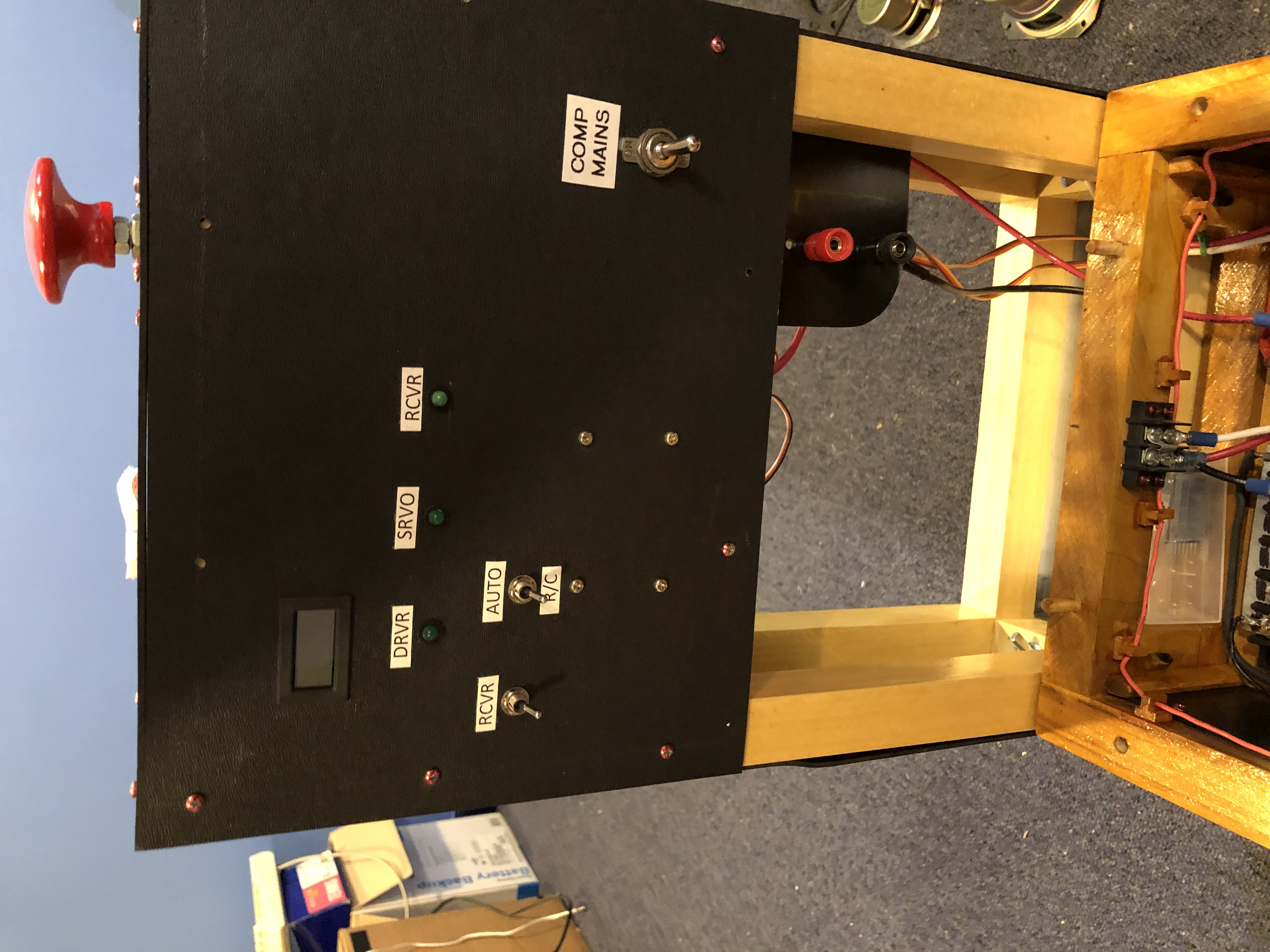
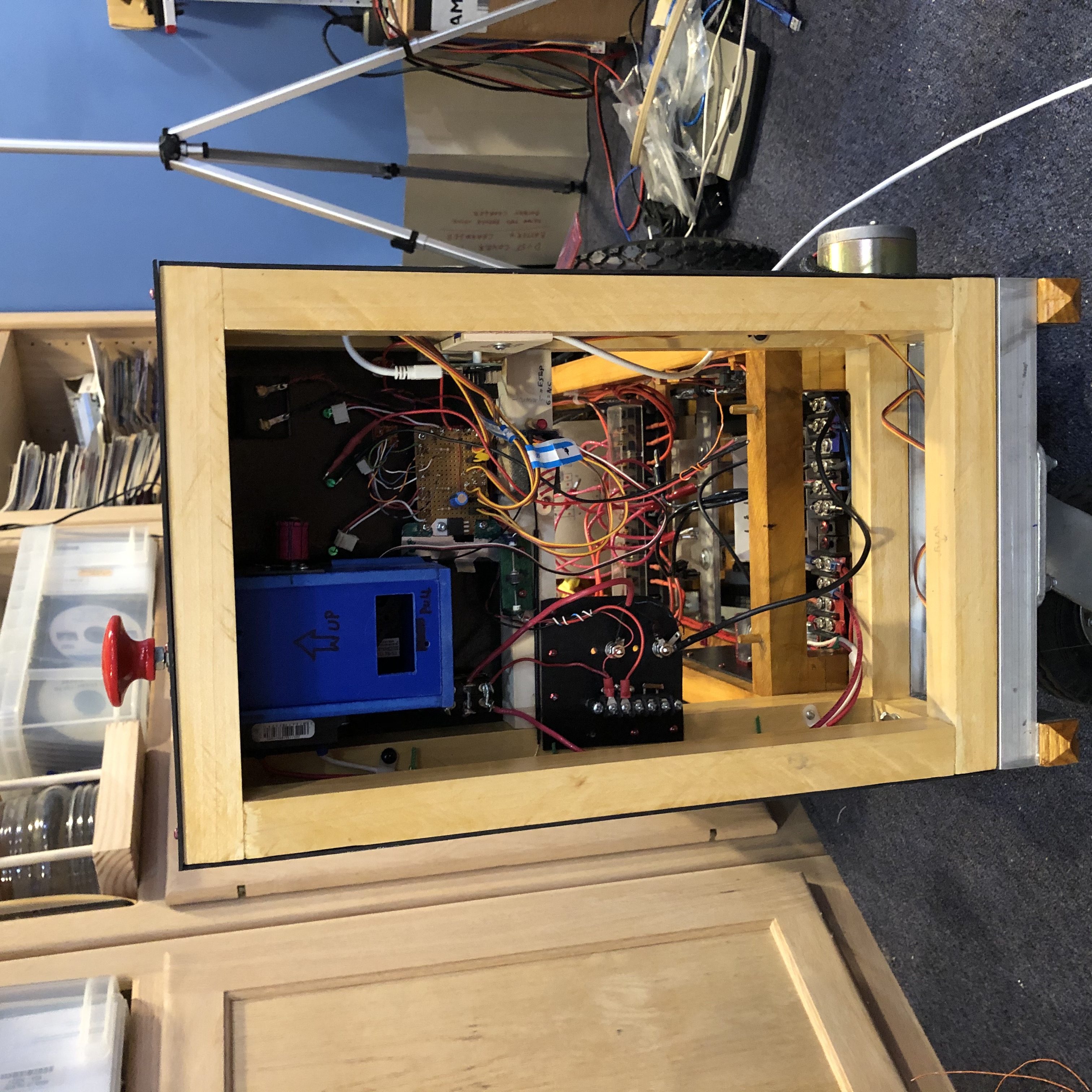
Each section is modular, and can be removed for easier access
to it's internal components
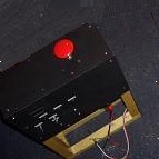
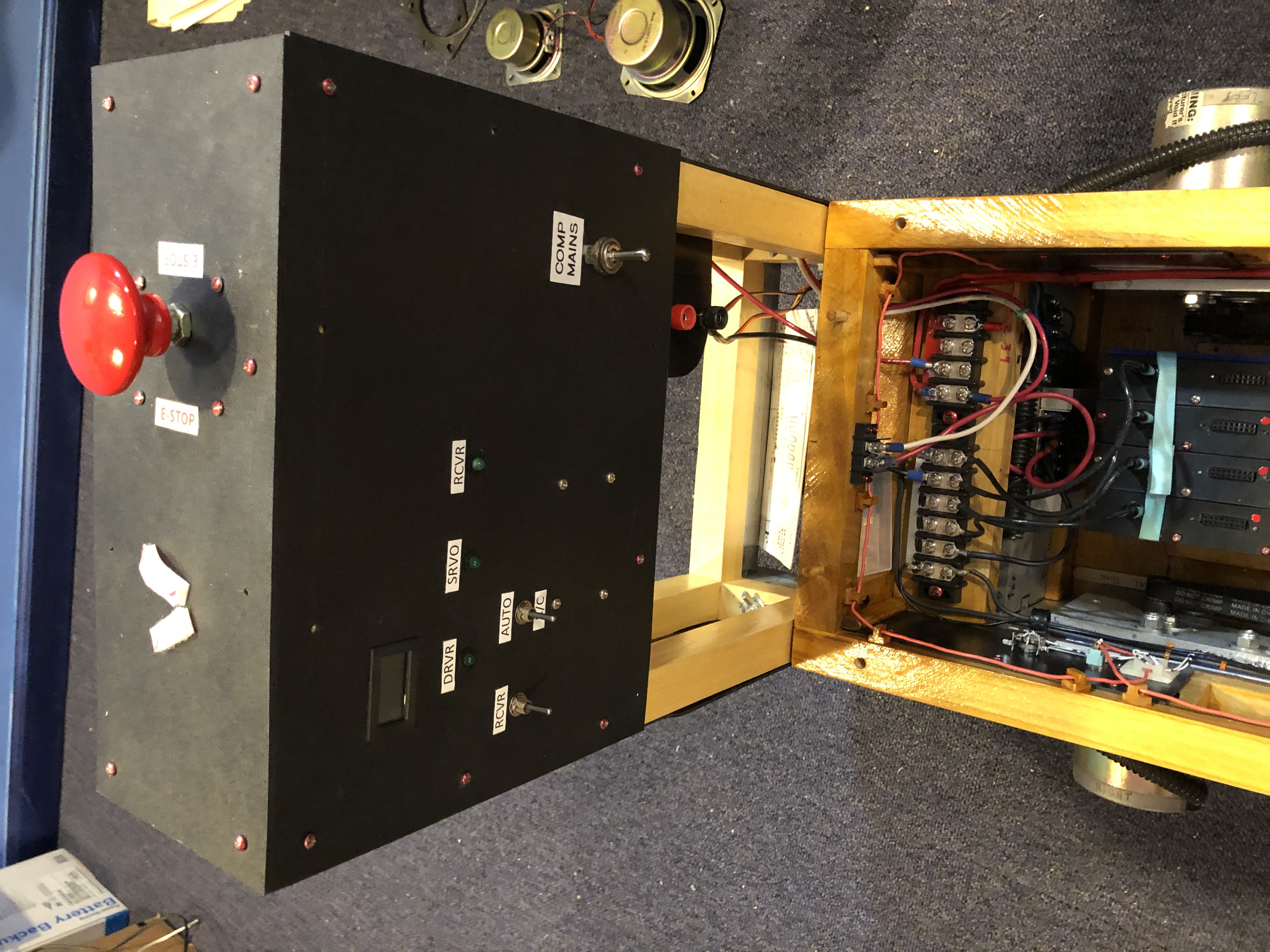
The front of the panel contains 3 indicator LEDs and 3 switches.
The large switch on the lower right, controls the power to
the computer section.
This switch can remove all power from the main motor driver.
The switch is mounted here, at a certain height above ground,
as per the specs of an old "NASA Grand Challenge".
This switch can be pressed manually, or it can be pulled down,
under remote control, by an internal servo motor.
On the front of the panel, in the upper left, is a small volt meter
- The main motor driver
- The servo controller board
- The R/C receiver.
The switch marked RCVR, controls power to the R/C receiver.
The switch marked AUTO - R/C, switches the main motors between Autonomous control (Computer) and Remote control,
via a standard R/C hobby transmitter.

The "RC / Auto" Switch allows me to drive the robot around
with a radio control, and then give the control back to the
computer software.
the Volt Meter, The R/C radio receiver, a servo controller board
and switches for the various optional working modes.
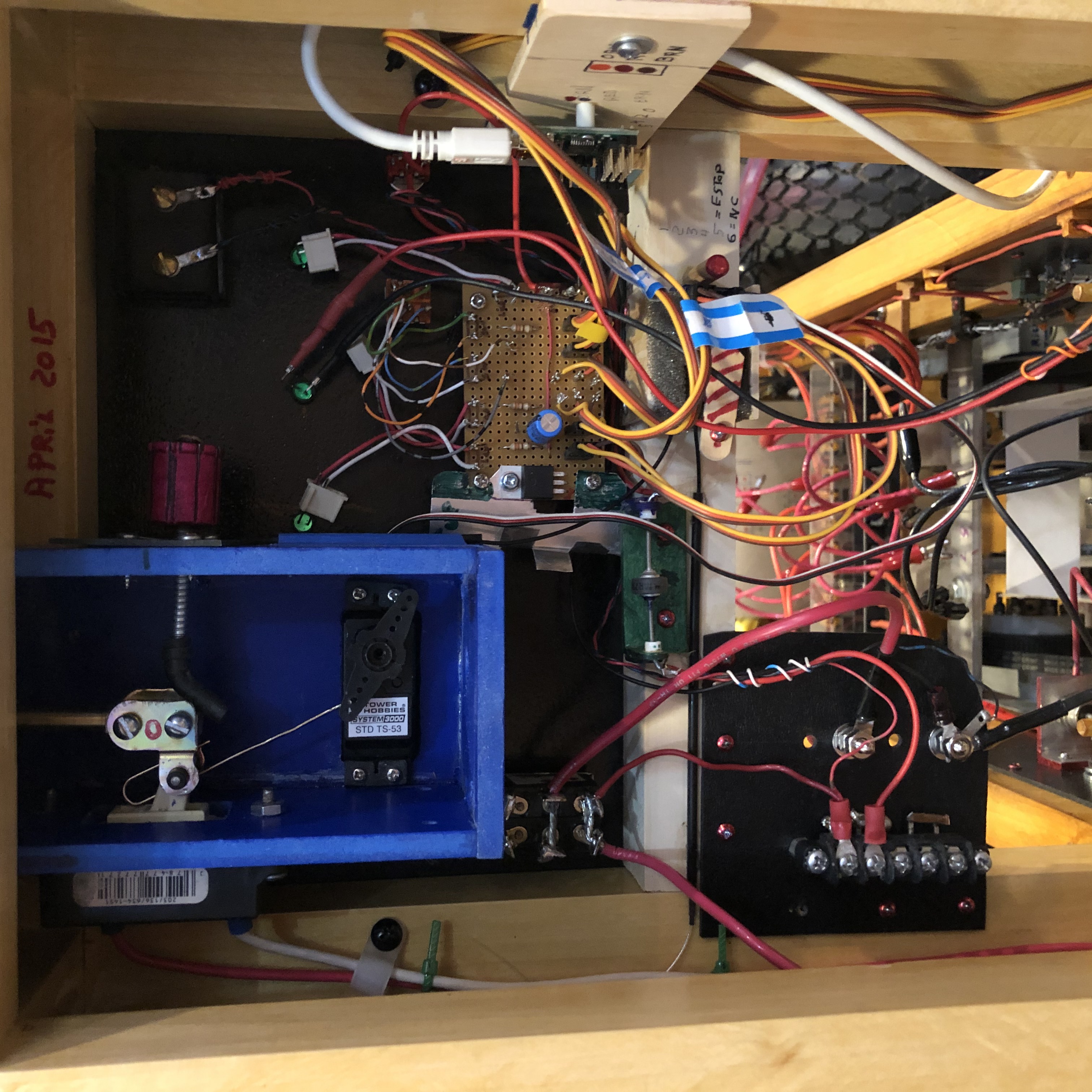
inside the blue box.
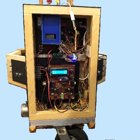
I completed the software to read the data from the Arduino on the Odometry board.
As of 6/10/2025, I am modifying the Odometry board to accept
analog voltages from some new 'current sensors' that I want to
install on the main drive motors.